The goal of vibration testing is to reflect the operational environment of a product as closely as possible. However, engineers may manipulate a vibration signal to meet the shaker system limits or test objectives.
Clipping—a method of signal manipulation—limits the drive voltage peaks, but many incorrectly believe it also limits the peak accelerations measured on the device under test (DUT). Therefore, Vibration Research (VR) has previously dissuaded engineers from using clipping to protect a shaker or DUT, as it does not function well for this purpose.
Yet, engineers still apply these standard methods because they want to protect their shakers from damage. Therefore, VR developed a new signal clipping method that manipulates the control rather than the drive. In the past, VR only suggested signal clipping to limit the drive voltage. Now it can confidently recommend clipping on the control to meet shaker limits.
Most modern vibration controllers assume a Gaussian distribution of random vibration. Statistically, this means random vibration data have a symmetrical distribution around the mean value.
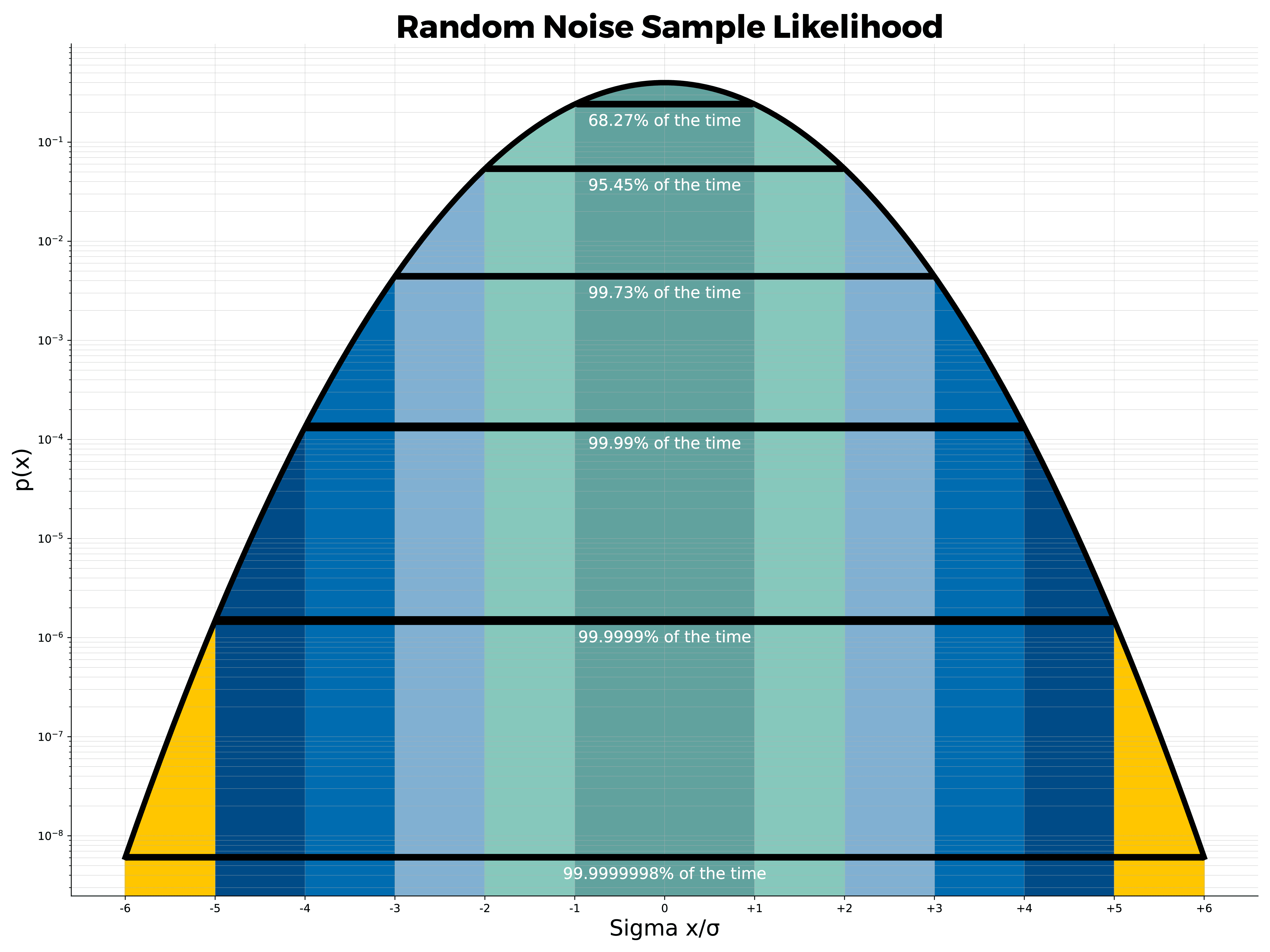 A Gaussian distribution indicates how many values fall within a certain standard deviation from the mean value of 0. The kurtosis—or the deviation of acceleration peaks from the mean—of Gaussian random data falls within ±3 sigma (σ) 99.73 percent of the time. The remaining percentage can be significant depending on the control system and device under test.
The probability of a Gaussian random signal falling within ±4σ is 99.99 percent. However, peaks up to 5σ (5x the test’s root-mean-square (RMS) level) or more are possible. RMS determines the average intensity (amplitude) in the random spectrum. These peaks may exceed the shaker limits for acceleration, velocity, or displacement (stroke) or damage a sensitive product.
Standard clipping methods limit, or clip, the voltage of the drive output, which reduces the extreme voltage peaks but distorts the signal so that it is no longer Gaussian. These methods give the illusion of minimizing constraints on the shaker system but only affect the drive output.
Experiments by George Fox Lang and Philip Van Baren found that clipping the drive signal does not produce an equivalent limit of the control acceleration [1]. This finding means that standard clipping does not limit the movement on the shaker table. It protects the amplifier but not necessarily the shaker or DUT.
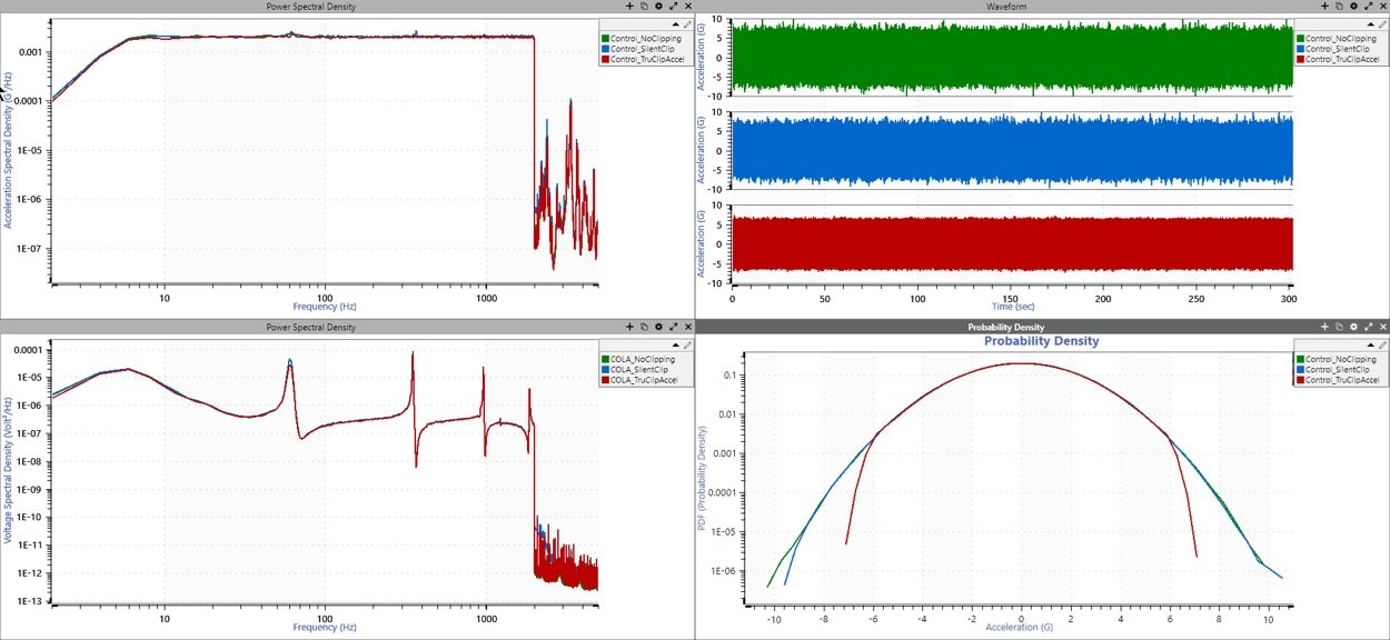
Additionally, the resulting signal’s response may not show indications of clipping, but its statistics may. A clipped signal will generate flat spots, and sharp transitions in the time waveform will lead to high-frequency distortion in the frequency domain analysis graphs (FFT, PSD, etc.). While the in-band PSD will only be slightly affected by this distortion (or not at all), it will increase the out-of-band energy, especially in the upper-frequency band. Moreover, a product may be undertested if the test profile omits high-amplitude peaks.
Engineers apply standard clipping thinking it will protect their shakers from damage. They require a method where they can be confident that the clipping will change the shaker motion statistics.
TruClip is a new clipping method developed by VR that utilizes closed-loop control to reduce high sigma peaks on the shaker table. It applies clipping to the control measurement and minimizes the chance of exceeding acceleration, velocity, or displacement limits.
TruClip applied to acceleration data.
TruClip is an innovation that performs clipping on the control instead of the drive. The user can filter the signal to displacement, velocity, or acceleration before clipping to reduce sigma peaks on different measurement types.
Engineers typically turn to clipping when experiencing issues with shaker system control. Shakers have limits for force, mass, acceleration, velocity, displacement (stroke), and drive voltage. Scenarios in which engineers may apply clipping include:
Standard (voltage) clipping methods solely affect the drive output and reduce the voltage (and, as an effect, current). Engineers can apply standard clipping when testing near the amplifier’s maximum voltage/current limits. There is direct control of the voltage output, so voltage clipping is precise. Engineers should not use standard clipping methods to meet shaker/DUT limits.
TruClip affects the control measurement on the shaker and reduces peak acceleration, velocity, or displacement. Engineers can apply TruClip when running a test near the maximum A/V/D of the shaker. There is always some error in the control, which leads to some variability in the precision of TruClip. The better the shaker system, the more accurate the clipping.