
Assessing a signal environment to ensure proper deployment, installation and operation of wireless networks is no easy task. From natural obstructions such as mountains to man-made obstacles like wind turbine generators, signal integrity is one of the biggest concerns for wireless service providers, public safety users, LMR operations and government officials.
Another signal integrity challenge involves the ever-crowding RF spectrum. The roll out of 4G, especially LTE, as well as P25 radio systems and NXDN LMR systems are adding to interference concerns. Moreover, utility companies are using two-way wireless communications for real-time monitoring and deploying of energy through the smart grid. Private wireless networks in professional buildings, medical facilities and industrial operations are more common than ever.
The growing signal integrity concern even extends to the federal government. The Federal Aviation Agency (FAA) is now facing a new challenge, as wind turbine generators are affecting the radar cross section spectrum used to ensure the safe take off and landing of commercial aircraft.
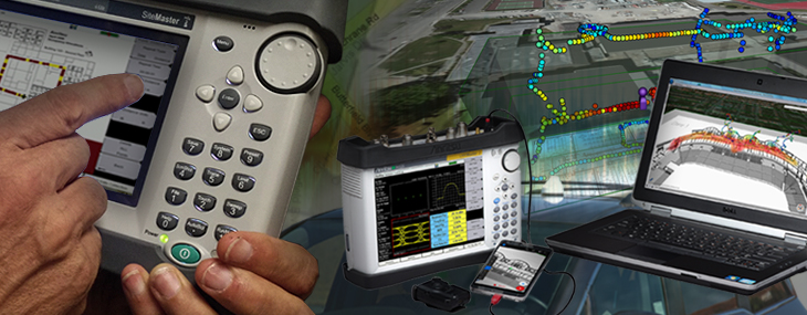
For all of these reasons, interference and coverage mapping has become an invaluable tool. Field technicians and engineers can integrate mapping tools into Anritsu handheld analyzers, including the Spectrum Master™ and LMR Master™, to most effectively monitor RSSI and ACPR levels, conduct BER mapping, and determine carrier-to-interference (C/I) ratio to ensure optimum network operation.
For outdoor applications, a GPS feature allows detailed maps of signal coverage throughout a network to be created. Indoor mapping tools permit floor plans to be integrated into the instrument, so users can better see potential sources of interference during network installation, and help determine the cause of signal problems when they do occur. Whatever is the reason for interference, Anritsu’s handheld analyzers and mapping tools can help find and correct it.
Measuring RSSI values is the crucial first step to determining coverage. Anritsu’s powerful spectrum analyzers can accurately measure RF power measurements over a wide frequency range, which, when attached with an antenna, become Received Signal Strength(RSSI). With Option 431, Coverage Mapping, the RSSI and ACPR measurements are combined with on-screen map displays to become a very versatile solution for mapping the coverage of RF transmitters.
There are two methods of coverage mapping– indoor mapping, which doesn’t require the GPS function, and coverage mapping with GPS. Option 31, GPS, is a welcome addition to the mapping process. With GPS on, the instrument conveniently pinpoints the user’s location on the map, and each recorded point is saved with the geo-coordinates.
Maps from both indoor and outdoor facilities and areas can be used with Anritsu’s handheld instruments. Compatible maps are easily created from Map Master, a convenient software program provided by Anritsu. Pictures of indoor facilities can be uploaded, or an address entered and the map captured.
With a touch of a button, coverage mapping can be started. The user has full control over the threshold values and measurement settings. Each measurement point is assigned a color correlating to the threshold values, and this fully customizable function allows for quick results.
After collection is finished, the data collected can be saved as a KML file, tab delimited, and/or a JPG. When coverage mapping with GPS, a KML files can be opened with a geo-viewer program such as Google Earth. Each colored point is then placed according to GPS location, and can be individually selected to review the recorded values. Data values, with or without GPS can be opened later with a datasheet viewer, such as Excel. The data is organized into columns, allowing for every point to be easily examined.
A mapping session can also be recalled at a later time, with the help of the KML file saved. In this way, multiple coverage mapping sessions can be combined, creating a thorough and complete coverage map.
Determining coverage has never been easier, with the powerful tools within coverage mapping. Users are provided with a thoroughly effective and economical method for mapping coverage.
In-building wireless communications are essential to provide communications for law enforcement activities, for emergency medical treatment, for fire suppression, for carrying on the business of government, and for providing communications in time of disasters. There is abundant news of in-building events where public safety personnel have been called in to resolve problems and to support health and welfare needs. In all of these cases, effective and reliable communications are necessary for these professionals do their jobs effectively.
Anritsu has recently partnered with TRX Systems to introduce the Anritsu MA8100A TRX NEON® Signal Mapper, a 3D in-building coverage mapping solution to provide coverage maps based on RF measurements from the Anritsu Handheld Spectrum Analyzers. The TRX NEON Signal Mapper application provides an Android user interface so in-building measurements can be made at specific map locations by simply watching the display of an Android smart phone or tablet and walking as needed within the map. The in-building location is provided by the NEON Tracking Unit worn on the operator's belt which is equipped with a gyroscope, accelerometer, barometric pressure sensor, and other sensors. The tracking unit communicates with the Android smart phone via a Bluetooth link and Anritsu instrument measurements are sent to the smart phone via a USB interface. The NEON Command Software application provides two and three-dimensional results to help view measurements in difficult to map locations such as stairwells and elevators.
Interfering signals are an increasing problem, due to the increase of the number of wireless devices and an ever crowded spectrum. Wireless technicians are often forced to carry a “kit” of radios, directional antennas, and paper maps to locate interferers. Anritsu provides a powerful battery operated instrument that interference maps efficiently, combining the functionality of an on-screen map display and a directional antenna. GPS, option 31, supplements the mapping process by pinpointing the user location and saving each data point with the geo-coordinates. Interference mapping, once tedious and unproductive, is made easy with option 25.
Maps of the desired location are created conveniently using Map Master, a software program provided by Anritsu. When creating maps, the user can upload a picture file of their own map, or generate one by inputting the desired address.
GPS conveniently pinpoints the user’s location relative to the on-screen map. With the use of a directional antenna, the direction of the strongest source of the signal is saved with a touch of a button. After multiple lines are recorded, the intersecting point determines the location of the interferer.
After finishing, the data can be saved as a KML, JPEG, or tab delimited file (.mtd). A geo-viewer program, such as Google Earth, opens the KML file and creates a digital orthophoto quadrangle view for each data point saved. Each point can also be selected, illustrating the values and GPS coordinates, for an in-depth reassessment. The tab delimited file can be opened with a spreadsheet viewer, such as Excel. Doing so provides info for each individual point– from basic information, such as time recorded, to the actual measurement values recorded.
The use of Option 25, interference mapping, exemplifies an innovative method to both locate and map interferers. The instrument’s on-screen touch display coupled with GPS support greatly aids and simplifies the tedious interference location finding. Finding interfering signals has been modernized, with Anritsu’s powerful handheld instruments.
The Field Master Pro MS2090A spectrum analyzer and NEON Signal Mapper MA8100A are the ideal solution for anyone conducting coverage testing of RF and microwave communications systems, including 5G systems operating in both FR1 (<6 GHz) and FR2 (>6 GHz) bands and testing of indoor DAS systems. This solution is capable of supporting both indoor and outdoor coverage mapping needs. When used outside and in sight of GPS satellites, the solution will use GPS data to continuously track the user while making measurements of signals up to 54 GHz. Where GPS is not available, the system uses a body-worn tracking unit and Android-based software to deliver 3D location and mapping of measurement data inside buildings, underground, and in other GPS-denied areas.
In addition to the unique 3D tracking capability, the NEON Signal Mapper MA8100A provides exceptional indoor coverage mapping capabilities. It eliminates the need to manually perform "check-ins" at each test point, provides more data than what can be gathered manually, and removes data recording errors caused by "guesstimating" locations in large buildings. The NEON solution delivers actionable data in areas not easily analyzed (such as stairways and elevators), enables quick analysis of signal coverage, and drives faster problem resolution by providing the industry’s only geo-referenced 3D visualization.
The combined solution leverages the industry-leading performance of the Field Master Pro, which has the highest continuous frequency coverage up to 54 GHz, real-time spectrum analysis bandwidth up to 100 MHz, and a ruggedized design to withstand the demands of field test. Its best-in-class performance includes a Displayed Average Noise Level (DANL) of <-160 dBm, Third Order Intercept (TOI) of typically +20 dBm, and phase noise of typically -110 dBc/Hz @ 100 kHz offset.
Data collection is simple and efficient using Anritsu’s Field Master Pro and NEON Signal Mapper solution. Collection time is greatly reduced and data is much more accurate as compared to using non-integrated solutions, where signal information is collected only in 2D at check-in locations or interpolated using the limited number of check-ins that have been performed. As a result, data from other systems is often sparse, inaccurate, and time-intensive to collect.