Smart Solutions. Proven Results.

IMV M Series Low Force Shakers

IMV M Series Low Force Shakers

IMV M-series
Silent model suitable for abnormal noise inspection

Compact and silent design, but also powerful enough for full-scale tests.


Request Quote Request
A Quote

Most Quotes sent in 3-4 hours
Contact Representative QUESTIONS?
ASK OUR EXPERTS

Contact your local W5 Representative
Product Details

Features

■Silent design featuring a built-in cooling fan
A DC-powered cooling fan is built into the shaker. Natural air-cooling is also used when the cooling fan is stopped for silent operation (with a reduction in performance).

Outward Dimensions

System Model Unit m030/MA1-CE m060/MA1-CE m120/MA1-CE m030H/MA1
System
Specifications
Frequency Range Hz 0-3000 0-3000 0-2000 1000-10000
Rated
Force
Sine lbf 67 135 270 85
Random lbf rms 47 94 189 60
Shock lbf 67 135 270 85
Maximum
Acc.
No load g 51 51 51 20
0.5 kg load g 28 35 42 16
1 kg load g 19 27 36 13
Maximum Velocity in/s 63 63 63 -
Maximum Displacement inp-p 1.0 1.2 1.2 -
Maximum Load lbs 33 33 265 33
Power Requirements kVA 0.4 0.7 1.1 0.5
Vibration
Generator
Model
m030-CE m060-CE m120-CE m030H
Armature Support Method
Diaphragm spring Diaphragm spring Air suspension Rubber spring
Armature Mass lbs 1.3 2.7 5.3 4.2
Armature Diameter φin 4.5 4.5 6.9 2.6
Dimensions
Diameter (Φ)
in 7.5 9 12.6 7.5
Height in 10 11 13 11
Mass lbs 49 90 245 66
Power
Amplifier
Model
MA1-CE MA1-CE MA1-CE MA1-CE
Maximum Output kVA 1.0 1.0 1.0 1.0
Dimensions Width in 17 17 17 17
Height in 6 6 6 6
Depth in 17 17 17 17
Mass lbs 55 55 55 55
Cooling Method
Air Cooling Air Cooling Air Cooling Air Cooling
Cooling Blower
Housed in
vibration generator
Housed in
vibration generator
Housed in
vibration generator
Housed in
vibration generator


* The displacement at the lower limit of frequency (1,000 Hz) and maximum acceleration (20 g) is so small that there is no certified value.
* Power supply: single-phase AC100 V/200 V or AC110 V/220 V or AC120 V/240 V ±10% 50/60 Hz. A transformer is required for other supply voltages.
* Insulation pad (W16.1 × H1.8 × D16.2 in) is standard equipment.


* The specification shows the maximum system performance. For long-duration tests, system must be de-rated up to 70%.
Continuous use at maximum levels may cause failure. Please contact IMV if your system operates at more than 70%.
* Frequency range values vary according to the sensor and vibration controller.


System Model Unit m130LS/MA1-CE


System
Specifications
Frequency Range Hz 2-1000


Rated
Force
Sine lbf 292


Random lbf rms 146


Shock lbf 292


Maximum
Acc.
No load g 13


0.5 kg load g 12


1 kg load g 11


Maximum Velocity in/s 39


Maximum Displacement inp-p 2.0


Maximum Load lbs 220


Power Requirements kVA 1.1


Vibration
Generator
Model
m130LS-CE


Armature Support Method
Air suspension


Armature Mass lbs 22


Armature Diameter φin 7.1


Dimensions Width in 16.1


Height in 23.3


Depth in 18.1


Mass lbs 550


Power
Amplifier
Model
MA1-CE


Maximum Output kVA 1.0


Dimensions Width in 17


Height in 6


Depth in 17


Mass lbs 55


Cooling Method
Air Cooling


Cooling Blower
Housed in vibration generator


* Power supply: single-phase AC100 V/200 V or AC110 V/220 V or AC120 V/240 V ±10 % 50/60 Hz. A transformer is required for other supply voltages.
* The specification shows the maximum system performance. For long-duration tests, de-rating by up to 70% must be applied.
Continuous use at maximum levels may cause failure. Please contact IMV if you use more than 70%.

* Frequency range values vary according to the sensor and vibration controller.


Head expander
Model Dimensions W × H × D (in) Mass (lbs) Maximum frequency (Hz) m030-CE m060-CE m120-CE
TBV-125-□-A 4.9 × 4.9 × t0.8 2.0 2,000  
TBV-200-□-A 7.9 × 7.9 × t0.8 5.5 1,500 *
TBV-315-□-A 12.4 × 12.4 × t1.2 18.7

1,000

  *
*TBV-400-□-A 15.7 × 15.7 × t1.4 31.7 600     *

Vertical auxiiary table

"-A” at the end of model number shows that material is aluminum alloy.
Add the vibration generator type where "□” is shown.

* A supplementary guidance system using linear bearings is used with the vibration generator when combined with the head expander. Armature mass is increased due to the addition of the guide support.

Slip table
Model Dimensions (in) Maximum frequency (Hz) Mass (lbs)
m030-CE m060-CE m120-CE
TBH-200 7.9 × 7.9 500 8.8 8.8 12.1
TBH-315 12.4 × 12.4 500 16.5 16.5 19.8
TBH-400 15.7 × 15.7 500 27.1 30.8

Horizonal Table

* Slip plate material is aluminum alloy.


2-axis changeover vibration shaker system

 m-series multi-axis system

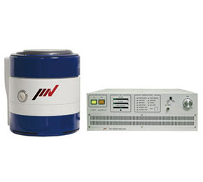
A range of small-size systems, including 2-axis and 3-axis simultaneous systems, employing the popular m-series vibration generators and patented Integrated Cross Coupling Bearing Unit (ICCU) multi-axis armature/load support technology.

  • Compact design
  • Low noise (ideal for squeak-rattle testing)
  • High precision measurement
  • Low power consumption
 System specifications
Rated force 270 lbf
Table size 7.9 × 7.9 in
Maximum frequency 500 Hz
Maximum
acceleration
3.0 g
Maximum
displacement
0.4 inp-p
Maximum
payload
22 lbs
Cooling method Air cooling
System noise 55 dB (A)
Weight Approx. 1,610 lbs
Power requirements 3 φ 200 V, 4 kVA

Corporate Headquarters
W5 Engineering | an R Source Company

Pacific NW/Main Office: (971) 244-8200
Greater Seattle: (425) 321-2757
Northern California: (510) 606-9090
Southern California: (818) 416-3487
Western Canada: (778) 650-5236
USA/Canada Toll Free: (866) 400-1300
© 2024, w5 Engineering - All Rights Reserved