
Power Supply Types, Capabilities, and Applications
The ideal DC power supply provides a constant DC voltage output independent of load current. As we know, no electronic product or anything else for that matter, performs as described in introductory electronics textbooks in which all designs have ideal components. So how do real power supplies differ from the theoretically ideal description? Let’s review how an actual DC programmable power supply works so we can answer that question. There are multiple types of power supplies with varying capabilities. So Let’s look at the types of power supplies and their capabilities. Programmable power supplies are used in a wide range of industries for numerous applications. We will look at some of the features that give power supplies the versatility to address a wide range of applications. In essence, what might appear to be a simple product is actually a sophisticated technology.
Figure 1 shows the basic circuit blocks of a DC power supply. The transformer galvanically isolates the AC line from the remainder of the circuitry. The transformer also steps down or steps up the voltage from the AC line depending on the desired maximum DC output voltage the supply is intended to have. The rectifier circuit block converts the AC voltage from the transformer to a unipolar AC voltage. Next, the filter block converts the Unipolar AC into an imperfect DC voltage with a ripple effect. The regulator adjusts the output voltage to the desired level and adds further filtering so that the output is a constant DC voltage.
The circuit blocks include many components, and none of them are ideal. Capacitors and inductors have parasitic resistance, parasitic capacitance (in an inductor), and parasitic inductance (in a capacitor). Transistors and diodes have I-V characteristics that change as a function of temperature. All components have tolerances on their values, consume power, have power limitations, and generate noise. These non-ideal characteristics contribute to a power supply not being a perfectly constant source of DC output.
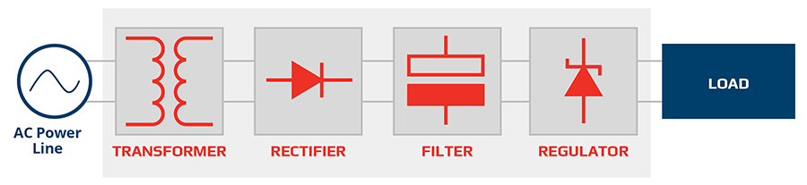 Figure 1. Generic block diagram of DC power supply
DC power supply outputs will not always deliver the exact output programmed by the user. Based on component tolerances, the manufacturer will define an accuracy for the DC output, an output accuracy or a display accuracy. The manufacturer may also specify a temperature coefficient to add to the output tolerance if the environmental temperature falls outside the temperature range in which the power supply has been calibrated. Another reason that the DC output will fall below a programmed value is that at high current loads, more voltage is dropped across the internal resistances of various components in the power supply. Manufacturers specify this effect as load regulation, a percentage error of full-scale voltage. For a complete determination of the output accuracy of a DC power supply, the load regulation error should be added to the output accuracy.
The DC supply will also have noise riding on the DC output. There is noise inherent in all electronic components related to electron motion and electron collisions in metallic structures. This noise is known as Johnson noise. Noise is also induced in a power supply’s output from conditions on the AC line, environmental electromagnetic interference (EMI), and stray currents on ground lines. Minimizing noise in a power supply, as with any electronic instrument, requires attention to the details of good design technique. However, no matter how good the design, noise will be on the DC power supply’s output.
There are two types of power supply topologies. Power supply designs can have either linear or switch-mode topologies. The differences in the design are in the rectifier block and the regulator block. Linear designs have power flowing continuously in the circuitry. Their designs have the benefit of low noise and low complexity, but they are not very efficient. Efficiencies for linear power supplies are below 50%. Switch-mode supplies, on the other hand, can have efficiencies in the 90% range, but they have much greater complexity and much higher output noise. Higher noise is due to active components, transistors, used as switches, turning power on and off at kHz rates. Switch-mode power supplies have the benefit of being smaller and lighter than comparably powered linear power supplies. A switch-mode supply can use a lighter weight and smaller transformer. Furthermore, the higher the switching frequency, the smaller all the inductive components can be.
While either topology is suitable for power supplies under a few hundred Watts, switch-mode power supplies are almost always used to design power supplies with power levels above 500 W and in the kW range. For kW power supplies, the transformer would be just too large and too heavy.
Most power supplies are unipolar instruments with positive polarity output. Voltage and current are both positive. They operate only in Quadrant I, as shown in Figure 2. Power supplies can also have more complex circuitry and operate in more quadrants. Bipolar output power supplies operate in Quadrant I and Quadrant IV. The output voltage can be either positive or negative, while the current is always positive. A third type of power supply can operate in Quadrants I and II. This type of supply is known as a bidirectional power supply. In Quadrant I, the supply is a DC voltage source. In Quadrant II, the bidirectional power supply has positive voltage, but negative current. The supply absorbs current and operates as an electronic load. Thus, a bidirectional supply combines the performance of two instruments, a DC power supply and a DC electronic load.
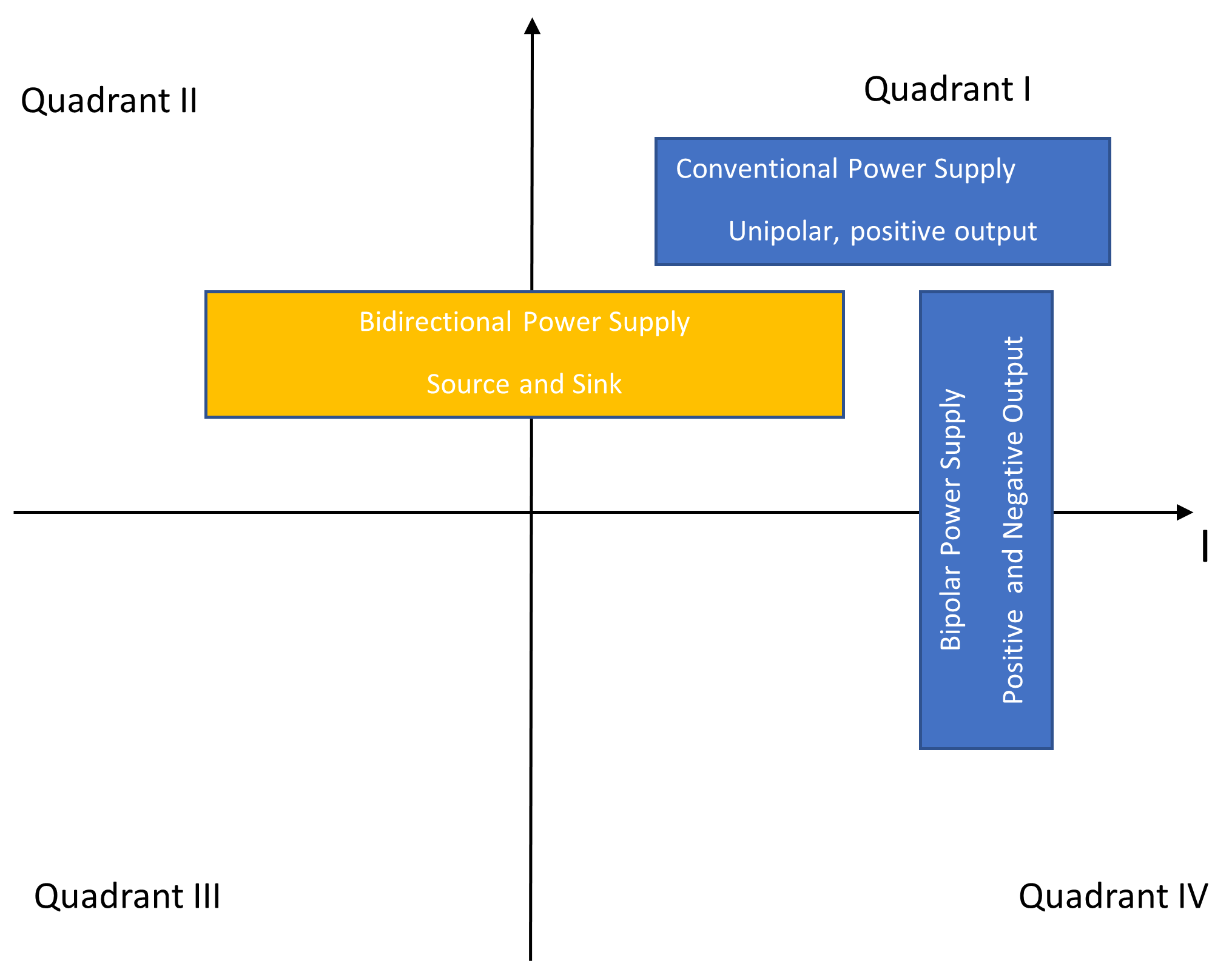 Figure 2. Three types of DC power supplies
Let’s provide a little more detail on the regulator circuit block. As well as filtering the output to provide a DC output with minimal ripple, the regulator maintains the output voltage at the adjusted or programmed level. We can model the regulator circuit as a feedback amplifier, as shown in Figure 3. The output voltage sensing circuit monitors the output voltage and feeds it back to the power amplifier. The voltage output of the power amplifier either raises or lowers its output based on the polarity of the voltage differential at the amplifier input.
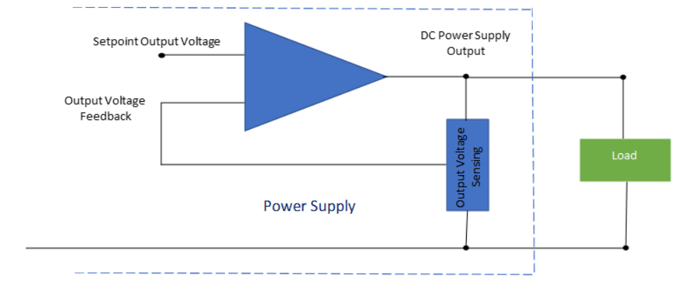 Figure 3. Power supply output stage showing voltage control (not showing output filtering)
Monitoring the voltage at the DC power supply output terminals is sufficient when the load draws a small amount of current. The voltage drop across the lead wires is insignificant at small load currents. However, with large load currents, the voltage drop across the lead wires can be substantial, and, the voltage applied to the load is lower than the programmed output voltage:
VLoad = VSupply – 2·VLead
We can correct for the lower voltage at the load if the DC supply is designed with 4-wire connections in which two wires supply power to the load and two wires sense the load voltage. Figure 4 shows a 4-wire connection to a load.
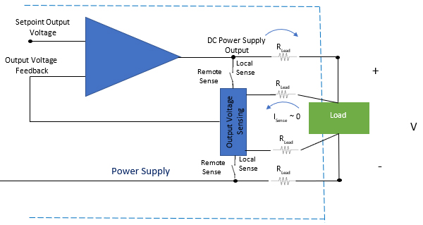 Figure 4. Output stage showing local and remote sensing
The Output Voltage Sensing circuit has a high input impedance, so the current drawn by this circuit is extremely small. With negligible voltage drop in the sense wires, the voltage sense circuit measures the actual voltage at the load and feeds that voltage back to the power supply’s power amplifier. The amplifier raises its output voltage by 2·VLead to compensate for the voltage drop in the leads. This feature is known as remote sensing and ensures the output at the load is the desired voltage. When not using a 4-wire setup, the regulator uses local sensing, which maintains the output voltage at the voltage on the output terminals. Using a 4-wire connection ensures greater accuracy of the voltage at the load.
Power supplies can deliver power to their load using different methods. A typical power supply will have an output I-V characteristic that is rectangular. The supply’s output can be any set of voltage and current values within a rectangle of the maximum rated voltage and current. The thick blue lines in Figure 5 illustrate a DC power supply with a rectangular I-V output characteristic. A second delivery method is known as autoranging. A DC supply with an autoranging I-V output characteristic has a combination of rectangular output and a hyperbolic output. The autoranging characteristic can supply a wider range of load current and output voltage than a comparably powered supply with a rectangular output. The black and red curve shown in Figure 5 is an example of an autoranging output characteristic. The benefits of the autoranging characteristic include:
Some autoranging power supplies have a hyperbolic output characteristic with full power delivery over a limited voltage range. Elektro Automatik (EA) power supplies have “true autoranging” in which the supplies can deliver full power output from the maximum rated voltage all the way down to 33% of that voltage. No other autoranging power supply has this level of performance. EA is unique in having this capability.
Thus, how a power supply outputs its power can determine its range of performance.
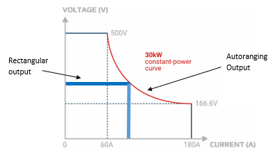 Figure 5. Comparison of a rectangular output characteristic with an autoranging output characteristic
Power supplies can have additional advanced features. Two examples include waveform generation and multiple control interfaces. Power supplies can have built-in function generators which allow the generation of waveforms on top of a DC bias level. Also, power supplies can have digital and analog interfaces to work with PCs, PLCs, and other instruments.
Bi-directional power supplies, when performing as a load, can have high efficiencies by converting the absorbed energy back to the AC power grid, up to 96% efficiency. These types of supplies are known as regenerative instruments.
In addition to supplying accurate, near-pure DC voltages, power supplies can offer more functionality such as the features I just described. The trade-off for the enhanced features is more design sophistication.
All industries that incorporate electronics in their products use DC power supplies. Design engineers use power supplies to develop new circuits and new products. Test engineers use power supplies to verify the performance of a manufactured product. Designs from all the industries that use electronic circuity and components have a wide range of power, voltage, and current requirements. For that reason, there are a very large number of power supply models with outputs ranging from under 100 W up to 60 kW. Models range from bench units for designers to rack mount units for test engineers.
As well as supplying power, design and test engineers often need to simulate products such as solar panels, batteries, and fuel cells. This is where a bi-directional power supply with a built-in function generator can act as a source to simulate a battery, a battery charger, a fuel cell, or a solar panel. Then the supply can act as a load to simulate a discharged battery or a circuit that a battery, solar cell, or fuel cell will power.
The built-in function generator can simulate noise and other disturbances on a DC power line to verify products can withstand levels of stress. The function generator can also simulate waveforms for testing to specific standards, such as those for automotive and avionics industries.
DC power supplies are essential instruments for the design and testing of all electronics. The extensive variation of electronic products has resulted in a wide range of power supply types and power supply features.
Power supplies are much more complex than their description in an introductory electronics textbook. They certainly do not perform as perfectly as the introductory textbook would imply. In describing how they work and the variations in performance, we hope you have a greater appreciation for the technology that goes into a product that all electronics engineers need.